An Internal QS6 PSU
Introduction
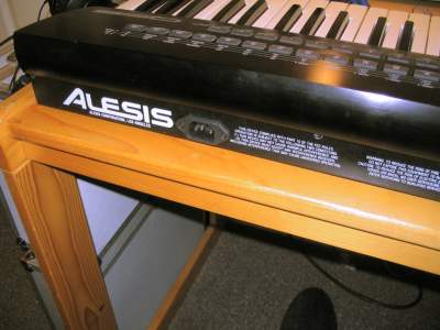
Hi! I'm Ben Weaver, and I'm an electronics engineer. I'm also a keen musician. That means I whenever I get a new synth to play with, I take it to bits and see if I can make it work better. This page is about modifying my Alesis QS6 so that it has an internal power supply. You may also like to read how I use cheap memory cards, and use cards greater than 8Mb.
One of the niggles I have about the QS6 is the external power supply. It's a "floor slug" type thing with a mains lead coming out of one side, and a low voltage cable coming out the other. I should point out that it's actually quite a physically rugged power supply (the one that originally came with my Korg X5 was rubbish!) but wouldn't it be nice if you could have an internal power supply? Well, I noticed that the QS6.1 had an internal power supply and that doesn't look too different from the QS6, and that got me thinking: I wonder if there's space inside the QS6 for the power supply?
Guess what? There is.
So natural events took their course, and here I am writing a page on how to get an internal QS6 power supply. It's not very technical, but you will need to do some metalwork (which takes time and patience) and some small bits of soldering and mains wiring. If you don't feel confident doing that then this probably isn't the mod for you. Get someone else to do it. And I should point out that obviously mains voltages are a bad thing, and if you prat around with them then you'll die. But if you know what you're doing, and you're confident, then they can be quite safe. I think of it like fire - obviously it's dangerous, but properly controlled then it's quite safe. But still, seriously, take care, and don't come running to me saying that you've burned your arm off.
What synths are we talking about here?
All of my work has been done on my QS6. I'd fully expect this hack to work just the same on the QS7 and QS8, but not on the QSR (because it's a much smaller chassis) or the QS6.1, QS7.1, QS8.1, QS6.2, QS7.2 or QS8.2 because they already have internal power supplies. If you do this mod on a QS7 or QS8 then please do get in contact - I'd love to know how you get on.
How does this modification work?
Dead easy. We take the existing power supply, change the cabling a bit, and mount it inside the synth to the right of the main PCB.
What will I need for this modification?
- An Alesis QS6, QS7 or QS8.
- An panel-mounting IEC (aka "Kettle Lead") socket.
- Some mains cable.
- Some heat-shrink sleeving.
- Nuts, bolts and a cable eyelet for the mains socket.
- An IEC mains cable with a 3A fuse.
- A small soldering iron and associated bits.
- Screwdrivers and bits, of course!
How do I do the modification?
Right - here we go. First of all, take the top off the synth. There are a number of small screws along the back and down the sides of the synth. The top should then lift off - but be careful as you will need to steer some studs at the front of the synth. Once the top is free, you can disconnect the two ribbon cables and the couple of round cables that connect between the main board and the top of the synth. Make sure you make a note of which way round the cables go.
Now unscrew the keyboard from the synth chassis. You'll need to disconnect the red-socketed ribbon cables from the keyboard, and unplug the aftertouch connector on the left of the main PCB.
Finally, unscrew the main PCB from the chassis. You don't really need to take it off, but I'd rather put it somewhere safe when I attack the rest of the chassis with power tools. There are three silver screws (two on the left, one on the right) holding it down, and you'll need to unscrew the five jack socket ring things on the outside. You won't, however, need to unscrew the card socket screws: they just hold the card slot bezel in place.
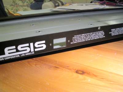
You should now have a plain chassis. Stand back and admire it. (My chassis is signed by someone famous - but that's another story!)
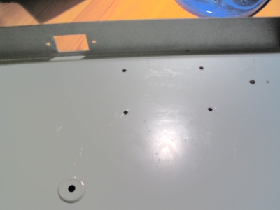
Okay now the fun starts. The next step is to cut out a hole for the IEC socket. I recommend putting the socket on the right hand side of the back panel (looking from the top). Offer the socket up and mark out with a pencil which bits of metal you need to remove. Remember the old adage: Measure three times, cut once. (Rather than the other way round.) Now drill/mill/file/nibble out the metal bits that shouldn't be there. Remember to drill two 3mm holes at either side of the socket ready for the screws to hold the socket in place. When you're done, you should end up with something like this:
Now, take the external PSU and take it to bits. It's held together with four screws that have a hex head. To get them out, you'll need a nutspinner. You might be able to get away with some long-nose pliers or even by drilling the screws out. Be creative, but try not to wreck the casing. It's always nice to do things in such a way that you can put them back to how they were before if you decide to. Once the PSU is in bits, take the bottom part of the casing. We're going to use it as a template for where we're going to put the PSU. In particular, it's going to go near the back of the chassis at the right hand side, about here:
Now take something like a fine pencil or sharp metal scewer, and mark out where the screw holes are on the chassis. Like this:
Next, drill out the holes. Make the holes about the same size as those in the bottom of the PSU case.
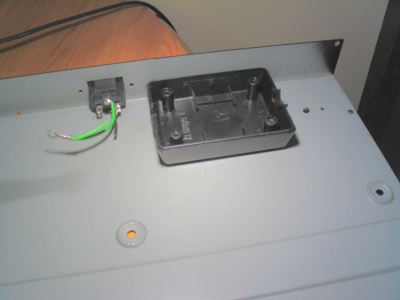
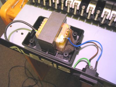
Okay. We're getting there. That's the boring stuff out of the way. Next, we add in the transformer from the power supply. I've unsoldered the cables from the transformer and put my own on because I can then keep the originals intact. You don't have to do that, but please do for goodness sake put some insulation on the terminals of the socket. I've used some nice heat-shrink sleeving, but you can use some insulating tape. Just make sure that you can't touch the live and neutral terminals on the socket. Run a short bit of earth wire from the earth pin on the socket to one of the screws that holds the socket in place. If you use a wire eyelet, then you'll get a really good electrical and mechanical connection.
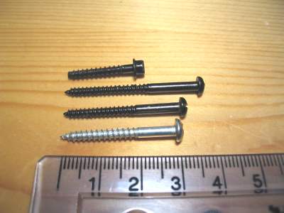
We're nearly done! You can now offer up the top part of the PSU casing, and put some screws in from the underside of the chassis to hold the whole thing together. You'll need to find some screws that are the same(ish) width as the original screws, but a bit longer. I found these quite hard to come by, but a rummage in several boxes found a few types that worked. In the picture below, the original screw is shown on the top. The three screws underneath all seem to work fine, but I wouldn't go with anything shorter than the shortest one here (30mm) or longer than the largest one (nearly 40mm). The thread width seems to be about 3mm.
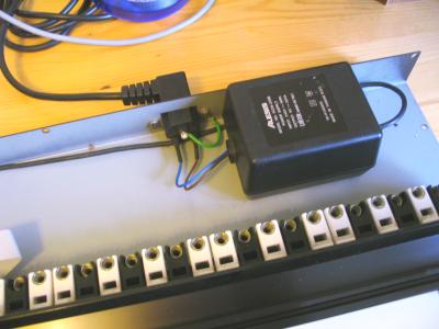
You should now have something that looks like this:
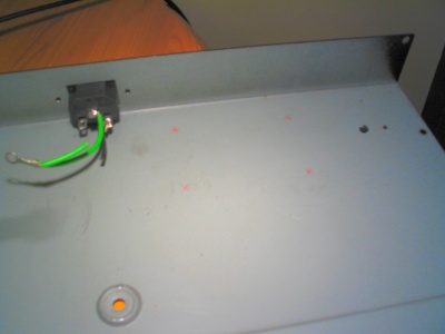
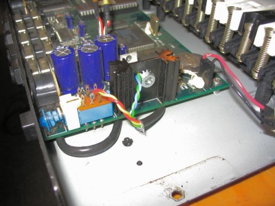
The final thing to do is to wire the low-voltage side of things in to the synth. As I said, I've used my own replacement cable. It, like the original, is 4-core split in to two pairs to give lower resistance - but don't worry if yours is different. You can get away with most types of cable. Some thin mains flex, for example, would be fine. I've run the cable underneath the main PCB so that it comes out on the left hand side. You can solder the two wires on to the pins on the original low-voltage socket, but I'm lazy and I just soldered one on to one of the middle pins on the power switch, and screwed the other on to the ground connection on the large heatsink on the extreme left of the main PCB. The low voltage supply is AC, so it doesn't matter which way round the wires go. Here's a picture of that bit:
Okay - all you need to do now is put the whole thing back together and you're done. Blimey - it's almost as if it had been done professionally!
- There's no fuse in the circuit here, so make sure you use an IEC lead with a 3A fuse.
- You might want to block off the original low-voltage power socket. If you had an extra external power supply and connected it to the synth and turned it on, then you'd probably get 240V back out of the mains socket we've just added in! That would be bad.
- You might like to think about what you might do with a low voltage AC socket on the back of the synth. For example, you could probably draw off power for driving a set of LEDs which you can use as worklights if you happen to be in a dark area, like on a stage. Be creative, but don't draw off "too much" power because the little transformer will probably keel over and die. How much is "too much" power? Well, for example, I wouldn't run another synth from it! And remember it's going to be AC. If you want DC then you'll have to rectify it. Want to talk through an idea you have? Get in touch with me!
Notes
"Help! I don't understand..."
I never was very good at writing stuff, so I've probably glossed over lots of important points in this explanation. If you're unsure of any point, then please do get in touch with me. I'll try to explain any point of the project in further detail. But please don't contact me asking silly questions like "What's a soldering iron?".
"Will you do the modification for me?"
No. It's a faff and you need an afternoon to do it. Once was enough for me!
How to contact me
If you have a go at doing this modification, then I'd love to hear how you get on.
I'm also keen to get hold of any technical documents for Alesis synths. I'd be really interested to have a look through the schematic for the QS6.
The best way of contacting me is through email. My email address is  .
.
This webpage and its content is © 2006 by Ben Weaver.