Using 16Mb Sample Cards
Introduction
Hi! I'm Ben Weaver, and I'm an electronics engineer. I'm also a keen musician. That means I whenever I get a new synth to play with, I take it to bits and see if I can make it work better. This page is about modifying my Alesis QS6 to use memory cards bigger than 8Mb. You may also like to read how I use cheap memory cards, and mounted the QS6 power supply inside the keyboard.
The Alesis QS range of synthesisers are famed for their ability to play sounds from user-programmable sample cards. These cards are linear PCMCIA flash cards, although there are pre-made ROM cards (known as QCards) available too.
Unfortunately, the synth can only use memory cards up to 8Mb. You can stick a larger card in, but normally you can't use the extra space. Having found out how to use large, cheaply available PCMCIA flash cards in the synth, wouldn't it be nice to be able to use all the space these cards have to offer? Well, guess what... you can! This page will tell you how to use 16Mb cards in your synth.
To use more than 8Mb, you need to make a small hardware modification to the synth. That means taking your synth apart, attacking it with some tools and then soldering a few wire in place. I'll talk you through it step by step, but please be aware that this modification would ideally be done by someone with some basic experience of electronics and soldering. If you're worried about doing this, then it might be wise to find someone to do it for you. The other thing that I should say is that doing this modification will almost certainly void any warranty you have on your synth!
What synths are we talking about here?
All of my work has been done on my QS6 (hardware revision A, software revision 2.00). In principle, I'd fully expect this hack to work just the same on any Alesis synth that can take PCMCIA sample cards. But you will probably find that the internals look rather different. If you want to attempt this modification on another synth, then get in contact and maybe we can work out what needs to be done.
How does this modification work?
The simple answer is this: The synthesiser can only ask for samples in an 8Mb memory range. If we want to use a card with a larger memory range available, then all we need to do is add an extra switch which will tell the memory card which 8Mb range we want to use. Put another way, we will store two 8Mb cards-worth of data on a single large card, and we will use a switch to tell the synth which "virtual" card to use.
Notes
The longer answer is this: When retrieving samples from the memory card, the synth places a numerical location on the sound generator address bus. Only 23 address lines are connected to the memory card - and this gives the 8Mb limit (223=8Mb). But memory cards larger than 8Mb will have more address lines available, giving access to more memory. What this modification does is to switch the 24th address line between logic '1' and logic '0'.
When it is logic '0', then the memory card will see the normal address given by the synth, and the synth will get data from the 1-8Mb memory range. When it is logic '1', then the memory card will see an address that is 8Mb larger than that given by the synth, and the synth will get data from the 9-16Mb range.
What will I need for this modification?
- An Alesis QS6, or similar synth as long as you know what you're doing.
- A small SPDT (Single Pole, Double Throw) switch.
- Three short bits of wire.
- A continuity meter.
- A Stanley knife.
- A small soldering iron and associated bits.
- Screwdrivers, of course!
How do I do the modification?
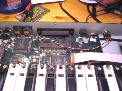
Okay, hold tight - here we go. First of all, take the top off the synth. There are a number of small screws along the back and down the sides of the synth. The top should then lift off - but be careful as you will need to steer some studs at the front of the synth. Once the top is free, you can disconnect the two ribbon cables and the couple of round cables that connect between the main board and the top of the synth. Make sure you make a note of which way round the cables go. Leave the two cables that come from the keyboard part connected.
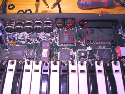
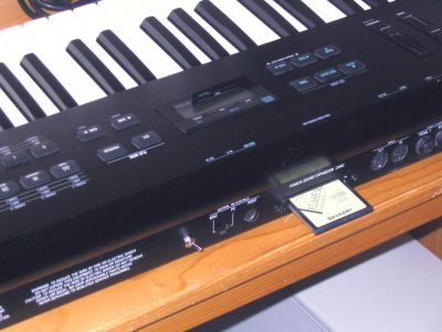
You should now see a view like the one shown below. We'll be mainly working in the area between the memory card slot and the sound generator chip (the big chip next underneath the MIDI sockets). I've put a red circle in the picture to highlight this area. If it looks different from what you're looking at, then you've probably got a different version of the synth. If that's the case, then please get in contact.
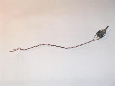
The next thing to do is to prepare a switch for our mod. Get hold of a SPDT switch, and solder three wires to it. Make each wire about 20cm long, and it will be helpful if they're different colours. I've used red, white and black here, and will refer to them by these names. You can, of course, use other colours, but don't mix them up!
Notes
SPDT (Single Pole Double Throw) switches are sometimes called On-On switches. They have two switching positions. They have three terminals, and the middle one is connected to one of the two outer ones depending on which way the switch is switched. If you can't get hold of a STDT switch then you could also use half of a DTDP switch. If you're in any doubt, get hold of a continuity meter and check that the switch works as expected.
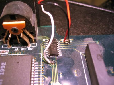
Looking a little closer at the area we're going to work in, find the group of three PCB tracks that run diagonally towards the MIDI sockets. They should run between the sound generator chip and a smaller chip nearer the back of the synth. Now look carefully at those three tracks. The one furthest away from the sound generator chip is the 24th address line. It's known as "A23" (23 because they start counting at zero). This is where we'll be doing the most of this modification.
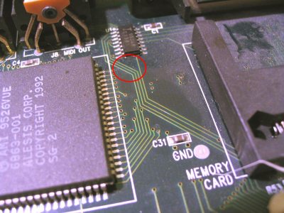
The next stage is to break this line with a Stanley knife (so that it's not driven), and then solder a wire (the middle one from the switch) to the side nearest the PCMCIA slot, so that we can drive the signal instead. It's not the easiest thing in the world, but it's do-able. Have a look at the diagrams below. Once you've located the track, you need to scrape the solder resist (the green painty stuff) from the track until you get nice shiny copper underneath. Keep scraping until you get a full clear track without any bits of solder resist on it. (See diagram 2 below.)
The next thing to do is to cut the track. Be careful here, as it would be very bad news if you slipped and cut the wrong thing. The way I find works best is to carve a small notch across the track. It won't look very nice, but it doesn't have to. The important thing is to make sure that the two sides of the cut track aren't connected. Use a continuity meter to check that they aren't connected. (See diagram 3 below.)
The final part here is to solder the white middle wire from the switch to the section of track nearest the PCMCIA card. It isn't very easy, so it's worth tinning both the end of the wire and the track first - that'll make it a lot easier. Once the wire is soldered, don't tug it because you might pull the track away from the PCB, and that would be bad news. (See diagram 4 below.)
Notes
If you don't fancy soldering to that tiny area of copper, then you can take the board out of the synth and solder directly to the pin on the PCMCIA card connector. It's pin 54. If you're unsure, then you can always get in contact and check.
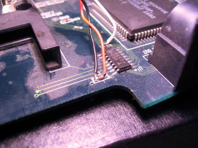
With one of the three switch wires in place, we need to solder on the other two wires. The good news is that they're much easier to do. They go to +5V and GND, which are conveniently available at either side of capacitor C1, which is located to the top right of the small chip that we've been working near. I've taken a couple of photos of where they go. Make sure you don't short out the two sides of the capacitor, because that would be sorting out the power supply. Use a continuity meter to check that they're not connected.
Here's a view of the red and black wires from the back of the PCB.
Okay - we're nearly there. What you need to do next is mount the switch somewhere convenient. When I did mine, I took everything off the main steel chassis and drilled a 6mm hole for mounting the switch, but there's obviously many ways of doing this. I'll leave it to your discretion.
All you need to do now is put the synth back together and enjoy the extra storage space!
How do I use this modification?
The first thing to do is to prepare a suitable sample card. To prepare a 16Mb sample card, you essentially take two small (up to 8Mb) card images and join them together. The card join point needs to be at exactly 8Mb, and the easiest way I can recommend of doing this is to use a small program I've written called join.exe. (Right-click the link and select "Save As..." to download the program.)
Once you've downloaded the program, using it is easy. Get a command window, and type:
join file1.img file2.img outputfile.img
This will take file1.img and file2.img, join them together, and save result as outputfile.img. It'll take a few seconds to do. You can join any type of sample card image (whether it's a .bin or a .img file), but don't get them mixed up!
Once you have your large file, burn it to a suitable flash card, using the method I described in my Cheap Sample Cards page.
- Make sure that the join.exe file is in the same directory as the image files.
- As an alternative to putting img2bin.exe in the same directory as the image files, you can put it in a folder which is in the OS search path - like C:\Windows or C:\WINNT.
- If your image files have spaces in the filename, then put the filename in speech marks, like "My File.img".
- If you're dealing with card images that are exactly 8Mb (8388608 bytes) in size, then you don't even need my "join" program. You can use the good old MSDOS "copy" command. Start up a command window, find your files and say:
Notes
copy /b file1.img+file2.img outputfile.img
Now you're all set. With the new switch in one position, you'll be able to use the first card image. With the switch in the other position, you get the other card image. You'll probably find that if you switch over during normal operation, the synth will keel over and stop responding in some way. The trick here is to turn off the synth, change the switch over, and then turn the synth back on.
"Help! I don't understand..."
I never was very good at writing stuff, so I've probably glossed over lots of important points in this explanation. If you're unsure of any point, then please do get in touch with me. I'll try to explain any point of the project in further detail. But please don't contact me asking silly questions like "What's a soldering iron?".
"Will you do the modification for me?"
Possibly... It won't be free, though!
Taking the project forward
I don't really intend to take the project forward any further, but in case anyone has any niggling little questions...
- "Can I use cards larger than 16Mb?"
- Yes. I've concentrated on 16Mb cards here because they're generally the most common sort largest available second-hand. Theoretically, you can use cards up to 32Mb. You'd need switch the A24 line too. That would either mean having two switches, or a BCD switch.
- "Could the synth auto-reset when you change the switch over?
- I guess so, although I reckon you'd need a few extra components added in. My thoughts are to decouple the switching signal, full rectify it, and then feed it to the system reset IC, which might need replacing. If anyone desperately needs this feature then get in contact.
- "Could you have a two-into-one card adaptor?"
- Yes, although you'd use a different circuit to do it. You'd also need to get hold of two card sockets and make a "fake" card to put in the synth. This is the sort of thing that happens in the QS6.1 synth.
- "Where did the A23 line go to before?"
- Good question. Normally I'd expect it to have been tied to ground, but I think it was actually being driven by the U1 IC. Maybe the system micro can actually change it autonomously. In that case, you could actually hack the firmware to get the synth to see cards larger than 8Mb, but that's way harder than the mod I've described here!
- "How do I do this modification on a different Alesis synth?"
- Another good question. It should be possible, but the PCB layout will probably be different. If you get in touch with me and we can work out what the layout is. I might even do the mod for you!
How to contact me
If you have a go at doing this modification, then I'd love to hear how you get on. In particular, I'd very much like to know what need to be done on different versions of the QS6 (there are six in total, I think. The outside looks the same, but the main PCB inside has a revision letter between A and F.) and other synths such as the QSR, QS7, QS8, QS6.1, QS7.1, QS8.1, QS6.2, QS7.2 and QS8.2.
I'm also keen to get hold of any technical documents for Alesis synths. I'd be really interested to have a look through the schematic for the QS6.
The best way of contacting me is through email. My email address is  .
.
This webpage and its content is © 2006 by Ben Weaver.